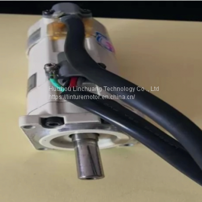
MHMA402A1G Panasonic Industrial Moule 30A Motor Servo-On Control Input
USD $1 - $1000000 /Unit
Min.Order:1 Unit
Quick Details View All >
Huizhou Linchuang Technology Co ., Ltd

MSMA011A1E Panasonic 100W Drives Control Equipment And Accessories

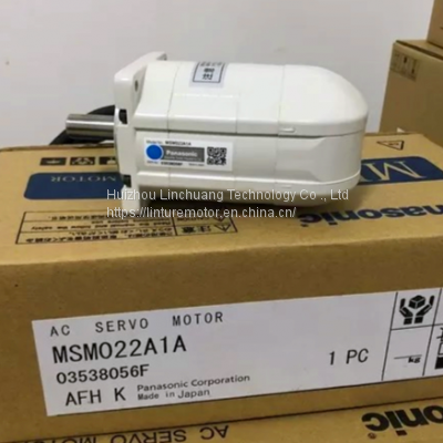
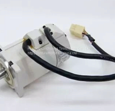
MSM082A4A Panasonic AC Servo Motor Industrial Computer Accessories

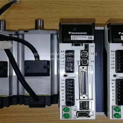
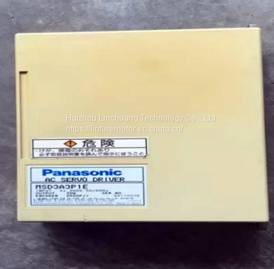
MSD5A3A1XX19 AC Electronic Driver Panasonic Servo Drive Systems
MFDHTB3A2 Panasonic Industrial Module Servo Motor and Controller
MHMJ082G1U Panasonic Low interference Industrial Servo Controller

MCDHT3520 Panasonic AC Servo Motor Driver 100-200v Control Supply
Product Details
| Brand: | Panasonic | Model Number: | MHMA402A1G |
|---|---|---|---|
| Input: | 30AC 200V 23.4A | Rated Rev: | 2000R/min |
| Reated Output: | 4.0kw | Rated FREQ: | 133Hz |
| High Light: | ac servo motor,electric servo motor | ||
Details
| Brand | Panasonic |
| Model number | MHMA402A1G |
| Input | 30AC 200V 23.4A |
| Rated Rev | 2000R/min |
| Reated Output | 4.0kw |
| Rated FREQ | 133Hz |
Specifications
Item | Specifications | ||
|---|---|---|---|
Control input | (1) servo-ON input (2) Alarm clear input (3) Gain switch input (4) Positive direction drive inhibit input (5) Negative direction drive inhibit input (6) Forced alarm input (7) Inertia ratio switch input | ||
Control output | (1) Servo-alarm output (2) Servo-ready output (3) External brake off output (4) At-speed output (5) Torque in-limit output (6) Zero speed detection output (7) Warning output (8) Alarm clear attribute output (9) Servo on status output | ||
Position control | Control input | (1) Deviation counter clear input (2) Command pulse inhibit input (3) Command division/multiplication switch input (4) Anti-vibration switch input (5) Torque limit switch input (6) Control mode switch input | |
Control output | (1) In-position output (2) Position command ON/OFF output | ||
Pulse | Max. command pulse frequency | 500 kpps (Optocoupler interface), 8 Mpps (When using line receiver input multiplied by 4) | |
Input pulse signal format | Differential input. Selectable by parameter. ([1]Positive/Negative pulse [2]A/B quadrature [3]Pulse/Direction) | ||
Electronic gear | Applicable scaling ratio: 1/1000 times to 8000 times Any value of 1 - 2 30 can be set for both numerator (which corresponds to encoder resolution) and denominator (which corresponds to command pulse resolution per motor revolution), but the combination has to be within the range shown above. | ||
Smoothing filter | Primary delay filter or FIR type filter is adaptable to the command input | ||
Analog | Torque limit command input | Individual torque limit for both positive and negative direction is enabled. | |
Torque feed forward input | Analog voltage can be used as torque feed forward input. | ||
Two-degree-of-freedom control | Available | ||
Anti-vibration control | Available | ||
Load variation suppression function | Available | ||
Speed control | Control input | (1) Internal command velocity selection input (2) Speed zero clamp input (3) Velocity command sign input (4) Control mode switch input | |
Control output | (1) Speed coincidence output (2) Velocity command ON/OFF output | ||
Analog | Velocity command input | Velocity command input with analog voltage is possible. Scale setting and command polarity vary depending on parameters. (6 V/Rated rotational speed: Default) | |
Torque limit command input | Individual torque limit for both positive and negative direction is enabled. | ||
Torque feed forward input | Analog voltage can be used as torque feed forward input. | ||
Internal velocity command | Switching the internal 8 speed is enabled by command input. | ||
Soft-start/down function | Individual setup of acceleration and deceleration is enabled, with 0 s to 10 s/ 1000 r/min. Sigmoid acceleration/deceleration is also enabled. | ||
Speed zero clamp | Internal velocity command can be clamped to 0 with speed zero clamp input. | ||
Two-degree-of-freedom control | Available | ||
Torque control | Control input | Speed zero clamp input, torque command sign input, control mode switch input. | |
Control output | (1) Speed coincidence output (2) Speed in-limit output | ||
Analog | Torque command input | Torque command input with analog voltage is possible. Scale setting and command polarity vary depending on parameters. (3 V/rated torque Default) | |
Speed limit function | Speed limit value with parameter is enabled. | ||
Full-closed control | Control input | (1) Deviation counter clear input (2) Command pulse inhibit input (3) Command division/multiplication switch input (4) Anti-vibration switch input (5) Torque limit switch input | |
Control output | (1) In-position output (2) Position command ON/OFF output | ||
Pulse | Max. command pulse frequency | 500 kpps (Optocoupler interface), 8 Mpps (When using line receiver input multiplied by 4) | |
Input pulse signal format | Differential input. Selectable by parameter. ([1]Positive/Negative pulse [2]A/B quadrature [3]Pulse/Direction) | ||
Electronic gear | Applicable scaling ratio: 1/1000 times to 8000 times Any value of 1 - 2 30 can be set for both numerator (which corresponds to encoder resolution) and denominator (which corresponds to command pulse resolution per motor revolution), but the combination has to be within the range shown above. | ||
Smoothing filter | Primary delay filter or FIR type filter is adaptable to the command input | ||
Analog | Torque limit command input | Individual torque limit for both positive and negative direction is enabled. | |
Torque feed forward input | Analog voltage can be used as torque feed forward input. | ||
Setting range of external scale | 1/40 times to 1280 times Although ratio of the encoder pulse (numerator) and external scale pulse (denominator) can be arbitrarily set in the range of 1 to 2 23 for the numerator and in the range of 1 to 2 23 for the denominator, this product should be used within the aforementioned range. | ||
Two-degree-of-freedom control | Available | ||
Anti-vibration control | Available | ||
Common | Auto tuning | The load inertia is identified in real time by the driving state of the motor operating according to the command given by the controlling device and set up support software “PANATERM”. The gain is set automatically in accordance with the rigidity setting. | |
Division of encoder feedback pulse | Set up of any value is enabled (encoder pulses count is the max.). | ||
Protective function | Hard error | Over-voltage, under-voltage, over-speed, over-load, over-heat, over-current and encoder error etc. | |
Soft error | Excess position deviation, command pulse division error, EEPROM error etc. | ||
Alarm data trace back | Tracing back of alarm data is available | ||
You May Like

New Products


Popular Searches
Recommended Products
Find Similar Products By Category


 Facebook
 X
X
 Pinterest
 Linkedln