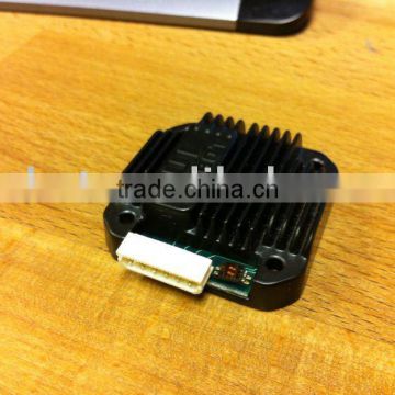
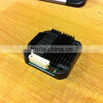
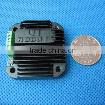
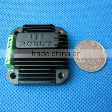
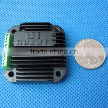
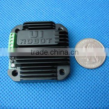
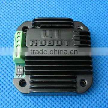
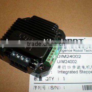
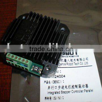
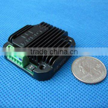
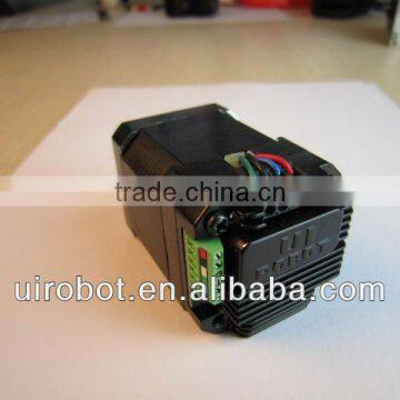
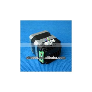
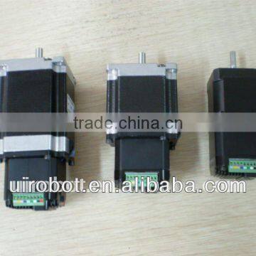
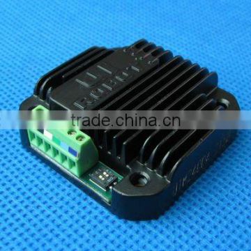
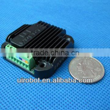
Two phase bipolar miniature Stepper Driver
USD $50 - $100 /Piece
Min.Order:1 Piece
Quick Details View All >
Shanghai United Intelligence Robotics Inc
Product Details
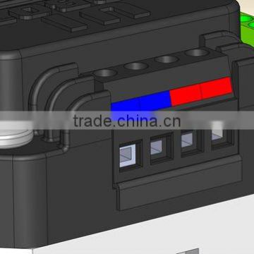
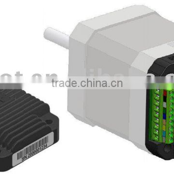
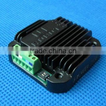
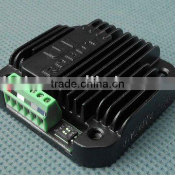
Stepper Driver Terminal Description

Stepper Driver Description of Screw Terminals
Terminal No. / Color | Description | Input | |||
MIN NOM MAX | UNIT | ||||
1 / Red | V+ | Supply voltage | UIM24004-8 | 12 40 | VDC |
UIM24002 | 10 35 | ||||
2 / Black | GND | Supply voltage ground | 0 | VDC | |
3 / White | Vcc | Opto-coupler common anode | 5(1) | VDC | |
4 / Green | DIR | Direction input(2) | GND Vcc | VDC | |
5 / Cyan | STEP | Stepping pulse input(3) | GND Vcc | VDC | |
6 / Blue | EN | Enable the Driver(4) | GND Vcc | VDC | |
Note:
(1) Please refer to “optically isolated input interface” section for details.
(2) Input is considered high level if this terminal is not connected.
(3) Low-level pulse duration should > 8μs. Maximum pulse frequency is 50 KHz.
(4) An active low-level input shuts down power supply to the motor. High-level input or left open makes the Driver fully working. When awaken from shutdown mode, wait 1 millisecond before sending pulse.
Note: To avoid damaging, make sure the phase winds are connected correctly. Resistance between leads of different phases is usually > 100KW. Resistance between leads of the same phase is usually < 100W.
|
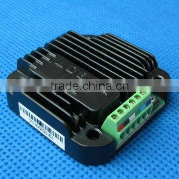
Motor Wiring Pads (at the bottom of the stepper driver)
Pad A + / A- : Connect to the stepper motor phase A
Pad B+ / B- : Connect to the stepper motor phase B
Contact Supplier

You May Like
New Products


Popular Searches
Recommended Products
Find Similar Products By Category


 Facebook
 X
X
 Pinterest
 Linkedln