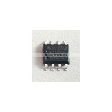
WS2821 ic chip
USD $0.28 - $0.33 /Piece
Min.Order:1000 Pieces
Quick Details View All >
Product Details
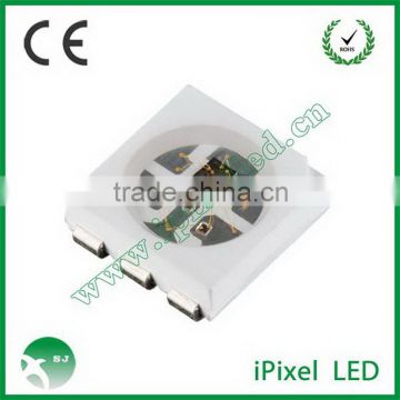
WS2821 ic chip
WS2821 is a LED driven IC,which adopts the parallel single wire control signal,owns the independent programmable address and large range programmable constant current,three channels output.
WS2821 has the power supply voltage stabilizing circuit,time base circuit,signal decoder block,data buffer,built-in address storage circuit.
WS2821 is mainly designed for the indoor/outdoor LED project lighting and decorative LED lighting system.
WS2821 owns three independent output driven channels,each channel can independent realize 256 gray PWM control,it can control the LED 256 gray without changing the LED light color,the default current is 19mA,meantime,users can use the external REXT resistor to adjust the output current.It support the output polarity reversal function.
WS2821 has the independent write code signal line,the address can be written in series at one time.
Main Features
Signal adopts the single line parallel connection type,any pixels’ failure won’t effect other pixel’s display effect.
Signal can compatible and expand the DMX512(1990) protocol signal.
Data transmission speed is 250Kbps~750Kbps.
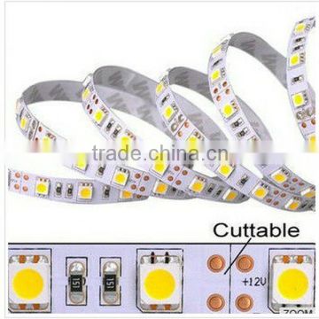
The built-in voltage regulator chip, 5V above 24V power supply only series resistance to IC VDD feet, without additional voltage regulator tube
WS2821 IC has VR-tube(voltage-regulator tube) built-in,for higher than 5V,lower than 24V’s power supply,only require one resistor being series connected to the IC’s VDD pin,no need to add the VR-tube outside.
Output voltage can bear 24V
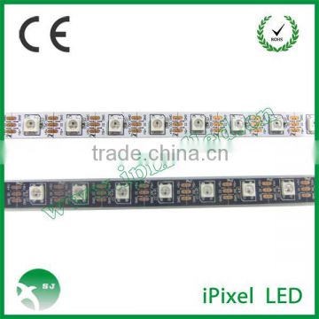
R/G/B out three channels’ output,each output driven channel has PWM circuit to control the gray,256 gray is adjustable
R/G/B output default current 19mA,maximum 60mA.
Storage space is built-in,support 1024 pixel’s parallel connection.
Support output polarity reversal function.
Main Application
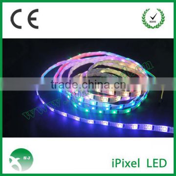
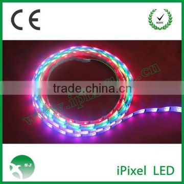
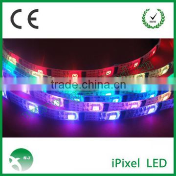
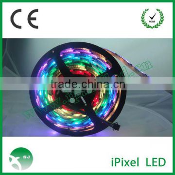
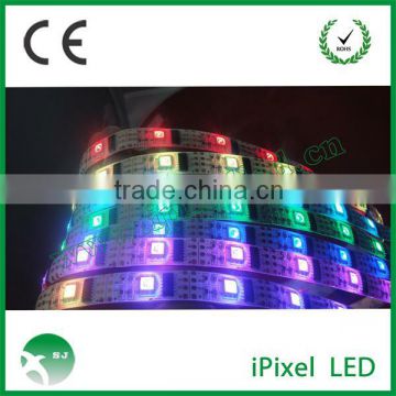
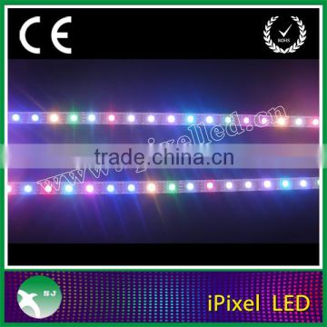
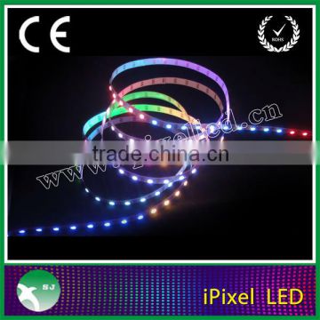
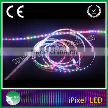
LED full color exposed light string
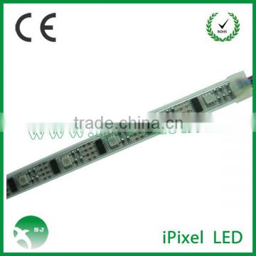
LED point light,LED module product
LED decorative lighting system
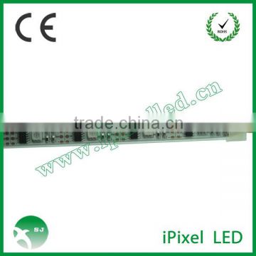
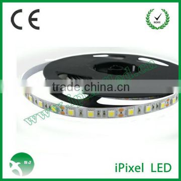
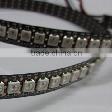
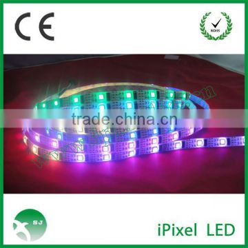
LED full color flexible strip
Other LED decorate products,DMX related products
PIN function
Pin NO. | Symbol | Pin Name | Pin description |
1 | GND | Chip Ground | Ground |
2 | NC | Non connection | Non connection |
3 | ADRO | Address output | Cascade address output port |
4 | ROUT | Driven output | R(Red LED)PWM control output,hight voltage PIN |
5 | GOUT | G(Green LED)PWM control output,hight voltage PIN | |
6 | BOUT | B(Blue LED)PWM control output,hight voltage PIN | |
7 | GND | Chip Ground | External adjustable resistor being connected to the ground,control OUT(R/G/B)output current |
8 | DAI | Data input | Gray control data signal input port |
9 | REXT | Output current set port | External resistor,connect with the REXT and GND,used to adjust the R/G/B OUT output current value |
10 | SPWM | PWM output polarity reversal | Default”1”:Three channel normal output,(Non connection or connect with VCC); For”0”,(SPWM connect with the GND),three channels output polarity reversal |
11 | ADRI | Address input | Cascade address input port |
12 | VCC | Chip power supply | Power supply,typical application is 5V |
13 | NC | Non connection | Non connection |
14 | NC | Non connection | Non connection |

Constant current parameter setting:
When the REXT bening no connected,R/G/B OUT three ports output current is 19mA(default value),users can connect the resistor at the REXT as well.Set the R/G/B OUT three ports current,is 19mA-mA,relations between the output current value and the resistance value are as follow
Contact Supplier

You May Like
New Products
Popular Searches
Recommended Products
Find Similar Products By Category

 Facebook
 X
X
 Pinterest
 Linkedln