2013 Hot-sale CDLF Vertical multistage pump
USD $100 - $800 /Piece
Min.Order:5 Pieces
Quick Details View All >
Umex (Ningbo) Imp. & Exp. Co., Ltd.
Product Details
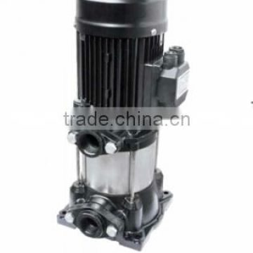
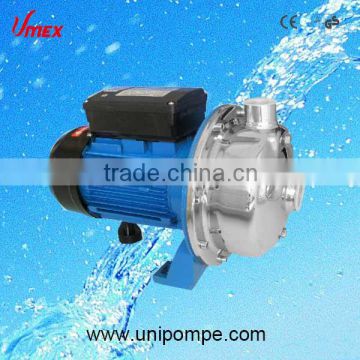
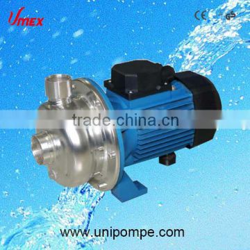
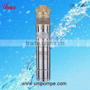
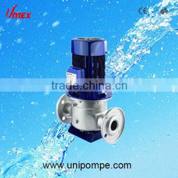
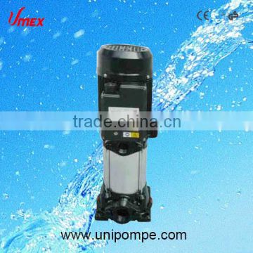
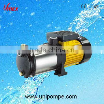
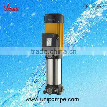
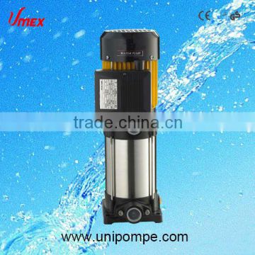
CDLF vertical multistage pump
Pump
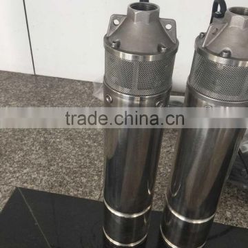
CDL/CDLF is a kind of vertical non-self priming multistage centrifugal pump,which is driven by a standard electric motor. The motor output shaft directly connects with the pump shaft through a coupling. The pressure-resistant cylinder and flow passage components are fixed between pump hesd and in-and outlet section with tie-bar bolts. The inlet and outlet are located at the pump bottom at the same plane. This kind of pump can be equipped with an intelligent protector to effectively prevent it from dry-running, out-of-phase and overload.
Electric motor
1.Full-enclosed air-blast two-pole standard motor.
2.Protection class: IP55
3.Insulation class: F
4. Standard voltage: 50Hz: 1 x 220-230 / 240V
3 x 200-220 / 346-380V
3 x 220-240 / 380-415V
3 x 380-415V
Minimum inlet pressure NPSH
In case that the pressure in pump is lower than the steam pressure used to convey liquid, the cavitations will occur. To avoid cavitations, a minimum pressure at the inlet side of the pump shall be guaranteed. The maximum suction stroke can be calulated with following formula: H=Pb x 10.2-NPSH-Hf-Hs
Pb=atmosphere pressure [bar]
(can be set as 1bar)
In a closed system, Pb means system pressure [bar]
NPSH=Nct positive suction head [m]
(It can be read out from the point of possible max. flow rate shown on NPSH curve)
Hf=Pipeline loss at the inlet [m]
Hv= Steam pressure [m]
Hs= Safety margin=Minimum 0.5m delivery head
If the calculated result H is positive, the pump may run under the max. Suction stroke H.
In case the calculated result H is negative, a delivery head of min.Inlet pressure is necessary.

Max.Working pressure
The following figure shows the limitation of pressure and temperature, which shall be in the scope as shown in the figure.
Max.Ambient temperature
When the pump operates under ambient temperature higher than 40 °C or under altitude higher than 1000m, because of low air density and poor cooling effects, the motor output power P2 will be decreased to certain extent. If the pump is operated under the above-said conditions, it should be equipped with motor of higher power.
Material CDL/CDLF1,2,3,4
NO. | Name | Material | AISI/ASTM |
1 | Motor | ||
2 | Pump head | Cast iron | ASTM25B |
4 | Mechanical seal | ||
5 | Top diffuser | Stainless steel | AISI304 |
6 | Diffuser | Stainless steel | AISI304 |
7 | Support diffuser | Stainless steel | AISI304 |
8 | Inducer | Stainless steel | AISI304 |
11 | Bearing | Tungesten carbide | |
12 | Impeller | Stainless steel | AISI304 |
13 | Shaft | Stainless steel | AISI304 |
14 | Impeller sleeve | Stainless steel | AISI304 |
15 | Cylinder | Stainless steel | AISI304 |
16 | Coupling | Carbon steel | |
CDLF | |||
3 | Seal base | Stainless steel | AISI304 |
9 | Inlet and outlet chamber | Stainless steel | AISI304 |
10 | Base plate | Cast iron | ASTM25B |
CDL | |||
9 | Inlet and outlet chamber | Cast iron | ASTM25B |
Product range
Description | CDL1 | CDL2 | CDL3 | CDL4 | CDL8 | CDL12 | CDL16 | CDL20 | CDL32 | CDL42 | CDL65 | CDL85 |
Rated flow[m3/h] | 1 | 2 | 3 | 4 | 8 | 12 | 16 | 20 | 32 | 42 | 65 | 85 |
Rated flow[l/s] | 0.28 | 0.56 | 0.83 | 1.1 | 2.2 | 3.3 | 4.4 | 5.6 | 8.9 | 11.7 | 18 | 24 |
Flow range[m3/h] | 0.4-2 | 1-3.5 | 1.2-4 | 1.5-7 | 5-12 | 7-16 | 8-22 | 10-28 | 16-40 | 25-55 | 30-80 | 50-110 |
Flow range[l/s] | 0.11-0.56 | 0.28-0.97 | 0.33-1.1 | 0.42-1.9 | 1.4-3.3 | 1.9-4.4 | 2.2-6.1 | 2.8-7.8 | 4.4-11.1 | 6.9-15.3 | 8.3-22.2 | 13.8-30.5 |
ure[bar] | 21 | 23 | 22 | 21 | 21 | 22 | 22 | 23 | 26 | 30 | 22 | 17 |
Motor power[kW] | 0.37-2.2 | 0.37-3 | 0.37-3 | 0.37-4 | 0.75-7.5 | 1.5-11 | 2.2-15 | 1.1-18.5 | 1.5-30 | 3.0-45 | 4.0-45 | 5.5-45 |
Temperature range[°C] | -15~+120 | |||||||||||
Max.efficiency[%] | 44 | 46 | 54 | 57 | 62 | 63 | 66 | 69 | 73 | 75 | 76 | 77 |
Type | ||||||||||||
CDL | · | · | · | · | · | · | · | · | · | · | · | · |
CDLF | · | · | · | · | · | · | · | · | · | · | · | · |
| CDL Pipe connection | ||||||||||||
| DIN Flange | DN25 | DN25 | DN25 | DN32 | DN40 | DN50 | DN50 | DN50 | DN65 | DN80 | DN100 | DN100 |
| Oval Flange | G1 | G1 | G1 | G11/4 | G11/2 | |||||||
| CDLF Pipe connection | ||||||||||||
| Din Flange | DN25 | DN25 | DN25 | DN32 | DN40 | DN50 | DN50 | DN50 | DN65 | DN80 | DN100 | DN100 |
| Cutting ferrule joint | · | · | · | · | · | · | · | · | ||||
| Pipe thread | · | · | · | · | · | · | · | · | ||||
PRODUCTION PROCESS SCHEME
Contact Supplier
You May Like
New Products


Popular Searches
Recommended Products
Find Similar Products By Category

 Facebook
 X
X
 Pinterest
 Linkedln