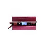
pwm dc motor solar charge controller with USB&DC 5A (CMTP01-DU05A)
USD $3 - $10 /Piece
Min.Order:30 Pieces
Quick Details View All >
Guangzhou Tianhe District Longdong Doxin Electronic Factory
New Solar charge controller with LED USB&DC 15A with good price and protection function
12V 24V 20A Tracer Solar Pump MPPT solar charge controller with USB
pwm solar system water pump panel charge controller 12v 10a with USB&DC
stage led street light solar charge controller with USB&DC 15A (CMTP01-DU15A)
5A wind generator battery solar hybrid charge controller inverter with LED
Product Details
pwm dc motor solar charge controller with USB&DC 5A (CMTP01-DU05A)
Light and timer control (Single timer and dual timer optional)
Ideal for public lighting area, such as street light, path way, garden lights, parking area,bus station etc.
Current: 5A/10A/15A/20A
Voltage: 12/24V auto work
Summarize
LC series solar charge controller adopts the most advanced digital technique and operates automatically.
The Pulse Width Modulation (PWM) battery charging can greatly increase the lifetime of battery.
Application:
Ideal for off-grid solar lighting system that needs light and timer control
Solar street light system
Solar garden light system
Solar billboard
Solar detection equipment etc.
Advantage:
Electronic Protections:
·Overheating
·Over discharging
·Over charging
·Load overload
·Load short circuit
·PV reverse polarity
·Battery reverse polarity
Temperature Compensation Coefficient
Description | Parameter |
Temperature Compensation Coefficient(TEMPCO)* | -30mV/°C/12V(25°C ref) |
* Compensation of equalize, boost, float and boost reconnect voltage
Features:
Electronic protection
Fully automatic operation
PWM charge mode (SOC)
Micro-controller digital accuracy
Suitable for all 12/24V DC lamps
Big terminals, big distance between terminals
Double digital LED display, numbers equal to timer setting
Temperature compensation (with external temperature sensor)
Indicator LED:
1. Charger LED is used to indicate the charging status of battery, LED turn off means charging stopped.
2. Battery Status indicator: RED ON when battery under voltage, please charging, GREEN ON when the battery full.
3. There is output and load can work if the Load LED is lighting. There isn’t output and the load can work is the Load LED off.
Notice:
1. Please carefully check and confirm the voltage before wiring the components of the solar panel voltage is 18V, battery 12V, 12V rated voltage of the load.
2. The rated current of solar panels and load must be less than the rated current of controller.
The specification: Error of 2%
Rated voltage | 12V | USB output voltage | 5V |
Voltage of stop power supply | 10.5V | USB output current | 550mA |
Voltage of recover power supply | 10.5V | DC output voltage | 10.5-14.5V |
Charging stop voltage | 14.4V | DC output current | 1.5A |
Rated of the charging current | 3.5/10/20/30/50/60/80/100A | Working temperature | -20 ~ +60°C |
Rated load current | 3.5/10/20/30/50/60/80/100A |
|
|
*USB, DC parameters only for some models.
Parameters may customized by customers.
CMTP01 series solar charge controller is a specially for the sunshine of the good development of a region and a separate simplified controller Suitable for 12V automatic control system, and some models with USB5V / DC12V output, to facilitate the use of smart devices and lighting.
1. Function:
Over-load protection
Short circuit protection
Reverse discharging protection
Reverse polarity protection
Protection from the lighting strike
Under-voltage protection
Over-charging protection
2. Connection ( As indicated in diagram ):
Open the top cover of controller and connect the wire with terminals follow the diagram on the top cover of it.
1. Connection the “+”, “-” Poles of the battery to the corresponding ports of controller ( the third and the fourth one from left ).
* The subsequent operation can be processed only if the load indicator ( mark: load ) flickers once and starts lighting after 30 seconds.
2. Connect the “+” “-” poles of the solar panel to the corresponding ports of controller ( the first and the second one from left).
3. Connect the “+” “-” poles of the load to the corresponding ports of connector ( the first and the sixth one from left ).


Contact Supplier

You May Like


New Products
Popular Searches
Recommended Products
Find Similar Products By Category