Pneumatic thermal conductivity detector
USD $1,000 - $10,000 /Set
Min.Order:1 Set
Quick Details View All >
Hebei Shengwei Ji Ye Frp Group Co., Ltd.
Product Details
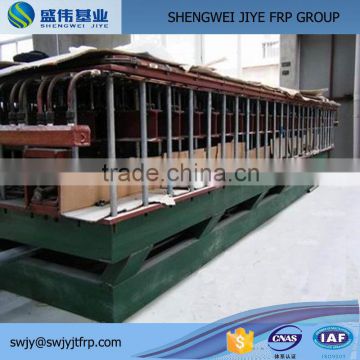
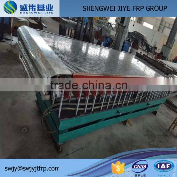
I. Overview
Thermal conductivity integrated test system is based on design GB/Tl0294-2008 and manufacturing standards for detecting thermal conductivity of insulation materials and special equipment.
Thermal conductivity (or resistance) is one of the main thermal performance of insulation materials. Thermal insulation material is the main symbol of identification of performance quality. In recent years, with the introduction of building energy regulations, China is increasing emphasis on building energy efficiency. Therefore, accurate measurement of the parameters is necessary. It has a great significance for a reasonable selection.
Automatic clamp device operating tips!
1. Open the sample box clamp device, the instrument will first open the top cover plate. The spacing is about approximately 45 seconds before the side cover automatically opens. During the intermediate reserved time of about 45 seconds, you need to manually open the door of the front cover. When operating the door of the front cover, remember don’t touch the place of the instrument where easy to pinch hand.
2. When locking the intensification device of the sample box, the instrument will first lock the side cover. After about approximately 45 seconds spacing cover plate will be automatically locked. During the intermediate reserved time of about 45 seconds, you need manually lock the cover door. When operating the door of the front cover, remember don’t touch the place of the instrument where easy to pinch hand.
2. The major technical indicators
Specimen size | 300X300 (mm) |
the thickness | 10 ~ 40 (mm) (preferably a thickness of 25mm) |
Thermal conductivity detection range | 0.001-1.0 (W / (m.K) |
Cold plate temperature | 5 °C ~ 50 °C |
Hot plate temperature | room temperature ~ 80 °C |
Testing accuracy | ≤2% |
Test repeatability | <1% |
Power supply voltage | AC 220V Total power 2KW |
Use of the environment | the laboratory with air conditioning 23 ± 2 °C |
Size | length × width × height: 800 × 600 × 1600 (mm) |
3. Working principle
Thermal conductivity detector uses dual specimen measuring device and guarded hot plate group which includes a heating unit and a cooling unit.
Heating unit is divided of the metering unit in the center and metering units surrounding the protection units separated by the gaps, and equipped with thermal insulation.
The heating unit adopts heater with dual hot sides. The cold plates and the double hot heater surfaces are symmetrically arranged. According to the thickness of the specimen set the mobile cold plate room. The test piece is vertically placed between two parallel plates with a constant temperature. Under the steady state the center measuring section of the test piece has constant heat flow. By measuring one dimensional constant heat flux Q, metering unit area A, the specimen’s cold and hot surface temperature difference T that flow through metering unit under the steady state, the specimen can be calculated thermal resistance R. Based on the thickness of the specimen it is possible to accurately calculate the thermal conductivity value of the specimen.
4. The main structural features
1. equipment of double specimens, double-sided hot plate, double-sided cold plate ues the world's most advanced polymer materials that has high temperature resisitance, thermal conductivity, softrness and other functions. It can be brought into close contact with the specimen to improve the measurement accuracy of thermal conductivity values.
2. The cooling system uses a closed compressing aggregation. Small running noise, fast cooling speed, long service life and other advantages.
3. The integral cooling method of the cooling unit of thermal conductivity detector and the evaporator not only saves raw materials, but also improves the cooling effect.
4. Clamping specimen is fully automated. Setting the space of mobile cooling unit and thermal unit depending on the thickness of the specimen only needs a single click of setup command on a computer.
5. Microcomputer control system consists of a computer and a printer to complete signal detection, acquisition and processing, temperature control, time control, the state of recovery and printing report.

Contact Supplier
You May Like
New Products

Popular Searches
Recommended Products
Find Similar Products By Category


 Facebook
 X
X
 Pinterest
 Linkedln