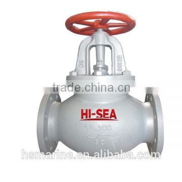
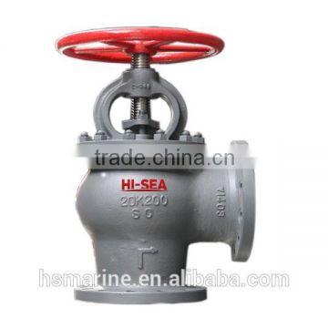
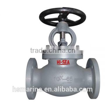
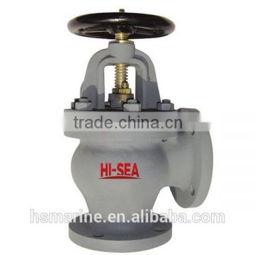
Marine Cast Steel Flanged Stop Check valve
USD $20 - $1,000 /Piece
Min.Order:1 Piece
Quick Details View All >
Chongqing Hi-Sea Marine Equipment Import & Export Co., Ltd.
Product Details
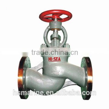
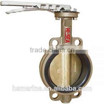
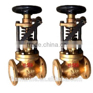
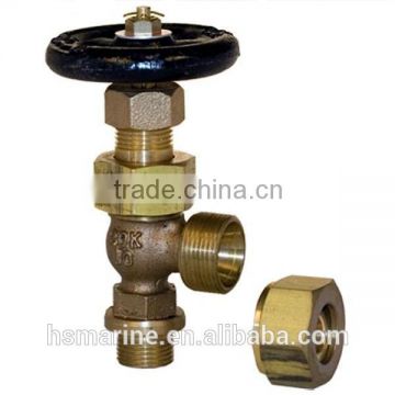
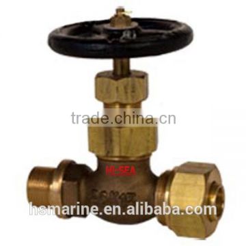
Stop Check Valve
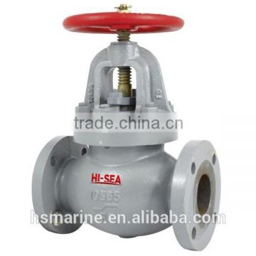
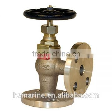
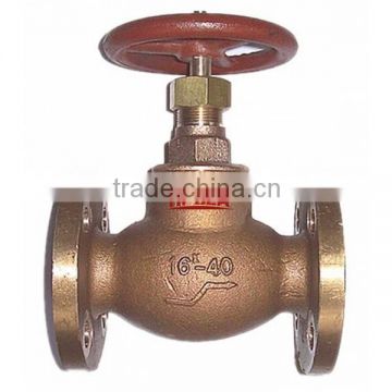
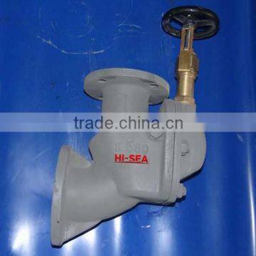
Marine Cast Steel Flange Stop Check valve:
1.Design standard:GB/T11698.
2.End standard:GB/T2501&GB/T569.
3.End type:Flange.
4.PN:1.0/1.6/2.5/4.0/6.4Mpa.
5.DN:20mm-300mm.
6.Main material:
7.Application:Oil piping,fresh water piping and steam piping.
8.Function:Such valves are used for on-off duty and preventing refluence.
9.Fundamental dimensions for Marine Cast Steel Flanged Stop Check valve :
Chart 1 Fundamental dimensions for A type and B type of globe check valves with PN1.0,PN1.6 and PN2.5Mpa:
PN Mpa | DN/mm | Construction dimension | Flange | Bolt | Weight/kg | ||||||||||
L/mm | H/mm | H1/mm | D/mm | D1/mm | D2/mm | d0/mm | b/mm | n | Th. | ||||||
Type A | Type B | Type A | Type B | Type B | Type A | Type B | |||||||||
1.0 | 65 | 290 | 115 | 310 | 277 | 115 | 155 | 123 | 104 | 15 | 14 | 6 | M14 | 14.9 | 12.9 |
80 | 310 | 125 | 345 | 304 | 125 | 170 | 138 | 118 | 15 | 14 | 8 | M14 | 19.0 | 17.9 | |
100 | 350 | 150 | 374 | 325 | 135 | 190 | 158 | 138 | 15 | 14 | 8 | M14 | 28.6 | 24.0 | |
125 | 400 | 175 | 426 | 366 | 155 | 215 | 183 | 164 | 15 | 14 | 10 | M14 | 38.2 | 33.7 | |
150 | 480 | 180 | 487 | 415 | 160 | 240 | 208 | 190 | 15 | 14 | 12 | M14 | 51.3 | 41.9 | |
1.6 | 125 | 400 | 175 | 465 | 405 | 155 | 225 | 187 | 168 | 17 | 15 | 10 | M16 | 45.4 | 38.9 |
150 | 480 | 180 | 524 | 452 | 160 | 255 | 217 | 196 | 17 | 15 | 12 | M16 | 58.9 | 51.7 | |
2.5 | 20 | 150 | 75 | 217 | 203 | 75 | 95 | 68 | 48 | 13 | 11 | 4 | M12 | 4.5 | 4.4 |
25 | 160 | 80 | 217 | 203 | 80 | 105 | 73 | 56 | 13 | 12 | 4 | M12 | 5.1 | 5.0 | |
32 | 180 | 85 | 236 | 216 | 85 | 115 | 83 | 64 | 15 | 13 | 6 | M14 | 6.9 | 6.1 | |
40 | 200 | 90 | 260 | 236 | 90 | 125 | 93 | 74 | 15 | 13 | 6 | M14 | 9.2 | 7.2 | |
50 | 230 | 95 | 288 | 258 | 95 | 135 | 103 | 84 | 15 | 13 | 6 | M14 | 12.9 | 12.7 | |
65 | 290 | 115 | 335 | 301 | 115 | 170 | 132 | 110 | 17 | 15 | 8 | M16 | 18.8 | 18.9 | |
80 | 310 | 125 | 362 | 321 | 125 | 185 | 147 | 126 | 17 | 16 | 8 | M16 | 24.8 | 22.7 | |
100 | 350 | 150 | 417 | 368 | 135 | 205 | 167 | 146 | 17 | 16 | 10 | M16 | 34.9 | 31.3 | |
125 | 400 | 175 | 481 | 432 | 155 | 240 | 196 | 172 | 21 | 19 | 10 | M20 | 52.2 | 47.9 | |
150 | 500 | 200 | 537 | 484 | 175 | 270 | 226 | 200 | 21 | 20 | 12 | M20 | 68.5 | 60.3 | |
Chart 2 Fundamental dimensions for A type and B type of globe check valves with PN4.0 and PN6.4Mpa:
PN Mpa | DN/mm | Construction dimension | Flange | Bolt | Weight/kg | ||||||||||
L/mm | H/mm | H1/mm | D/mm | D1/mm | D2/mm | d0/mm | b/mm | n | Th | ||||||
Type A | Type B | Type A | Type B | Type A | Type A | Type B | |||||||||
4.0 | 65 | 290 | 145 | 409 | 374 | 145 | 175 | 137 | 118 | 17 | 18 | 8 | M16 | 35.2 | 32.9 |
80 | 310 | 155 | 436 | 394 | 155 | 190 | 152 | 130 | 17 | 18 | 8 | M16 | 39.1 | 36.7 | |
100 | 350 | 175 | 466 | 416 | 175 | 225 | 181 | 157 | 21 | 21 | 10 | M20 | 53.3 | 44.7 | |
6.4 | 20 | 230 | 115 | 261 | 243 | 115 | 105 | 73 | 58 | 13 | 13 | 6 | M12 | 7.7 | 6.5 |
25 | 230 | 115 | 272 | 253 | 115 | 115 | 83 | 66 | 15 | 15 | 6 | M14 | 8.7 | 7.6 | |
32 | 260 | 130 | 304 | 281 | 130 | 125 | 93 | 74 | 15 | 17 | 6 | M14 | 10.3 | 9.3 | |
40 | 260 | 130 | 334 | 310 | 130 | 145 | 107 | 84 | 17 | 19 | 6 | M16 | 17.7 | 16.4 | |
50 | 300 | 150 | 354 | 323 | 150 | 155 | 117 | 96 | 17 | 20 | 6 | M16 | 22.3 | 20.5 | |
Chart 3 Fundamental dimensions for AS type and BS type of globe check valves with PN1.0,PN1.6 and PN2.5Mpa:
PN Mpa | DN/mm | Construction dimension | Flange | Bolt | Weight/kg | ||||||||||
L/mm | H/mm | H1/mm | D/mm | D1/mm | D2/mm | d0/mm | b/mm | n | Th. | ||||||
Type AS | Type BS | Type AS | Type BS | Type AS | Type AS | Type BS | |||||||||
1.0 | 200 | 600 | 275 | 621 | 543 | 275 | 340 | 295 | 268 | 22 | 24 | 8 | M20 | 109.0 | 104.0 |
250 | 730 | 325 | 721 | 623 | 325 | 395 | 350 | 320 | 22 | 26 | 12 | M20 | 167.0 | 160.0 | |
300 | 850 | 375 | 821 | 696 | 375 | 445 | 400 | 370 | 22 | 26 | 12 | M20 | 225.0 | 216.0 | |
1.6 | 100 | 350 | 175 | 417 | 368 | 175 | 220 | 180 | 158 | 18 | 22 | 8 | M16 | 35.4 | 33.2 |
125 | 400 | 200 | 465 | 405 | 200 | 250 | 210 | 184 | 18 | 22 | 8 | M16 | 50.5 | 46.1 | |
150 | 480 | 225 | 524 | 452 | 225 | 285 | 240 | 212 | 22 | 24 | 8 | M20 | 67.3 | 62.1 | |
175 | 540 | 225 | 573 | 505 | 225 | 315 | 270 | 242 | 22 | 24 | 8 | M20 | 92.1 | 87.8 | |
200 | 600 | 275 | 643 | 565 | 275 | 340 | 295 | 268 | 22 | 24 | 12 | M20 | 121.0 | 116.0 | |
250 | 730 | 325 | 744 | 646 | 325 | 405 | 355 | 320 | 26 | 26 | 12 | M24 | 180.0 | 173.0 | |
2.5 | 20 | 150 | 95 | 217 | 203 | 95 | 105 | 75 | 58 | 14 | 16 | 4 | M16 | 5.4 | 5.4 |
25 | 160 | 100 | 217 | 203 | 100 | 115 | 85 | 68 | 14 | 16 | 4 | M16 | 6.2 | 6.1 | |
32 | 180 | 105 | 236 | 216 | 105 | 140 | 100 | 78 | 18 | 18 | 4 | M16 | 8.9 | 8.3 | |
40 | 200 | 115 | 260 | 236 | 115 | 150 | 110 | 88 | 18 | 18 | 4 | M16 | 11.2 | 10.9 | |
50 | 230 | 125 | 288 | 258 | 125 | 165 | 125 | 102 | 18 | 20 | 4 | M16 | 14.5 | 14.2 | |
65 | 290 | 145 | 335 | 301 | 145 | 185 | 145 | 122 | 18 | 22 | 8 | M16 | 21.9 | 20.6 | |
80 | 310 | 155 | 362 | 321 | 155 | 200 | 160 | 133 | 18 | 24 | 8 | M16 | 28.9 | 25.8 | |
100 | 350 | 175 | 417 | 368 | 175 | 235 | 190 | 158 | 22 | 24 | 8 | M20 | 40.1 | 37.8 | |
125 | 400 | 200 | 493 | 432 | 200 | 270 | 220 | 184 | 26 | 26 | 8 | M24 | 60.3 | 58.1 | |
150 | 180 | 225 | 556 | 484 | 225 | 300 | 250 | 212 | 26 | 28 | 8 | M24 | 79.9 | 73.7 | |
Chart 2 Fundamental dimensions for AS type and BS type of globe check valves with PN4.0 and PN6.4Mpa:
PN Mpa | DN/mm | Construction dimension | Flange | Bolt | Weight/kg | ||||||||||
L/mm | H/mm | H1/mm | D/mm | D1/mm | D2/mm | d0/mm | b/mm | n | Th. | ||||||
Type AS | Type BS | Type AS | Type BS | Type BS | Type AS | Type BS | |||||||||
4.0 | 65 | 290 | 145 | 409 | 374 | 145 | 185 | 145 | 122 | 18 | 22 | 8 | M16 | 37.8 | 36.4 |
80 | 310 | 155 | 436 | 394 | 155 | 200 | 160 | 133 | 18 | 24 | 8 | M16 | 42.9 | 40.3 | |
100 | 350 | 175 | 466 | 416 | 175 | 235 | 190 | 158 | 22 | 24 | 8 | M20 | 54.1 | 51.5 | |
6.4 | 20 | 230 | 115 | 261 | 243 | 115 | 130 | 90 | 58 | 18 | 22 | 4 | M16 | 9.3 | 8.1 |
25 | 230 | 115 | 272 | 253 | 115 | 140 | 100 | 68 | 18 | 24 | 4 | M16 | 11.0 | 10.0 | |
32 | 260 | 130 | 304 | 281 | 130 | 155 | 110 | 78 | 22 | 24 | 4 | M20 | 13.1 | 12.2 | |
40 | 260 | 130 | 334 | 310 | 130 | 170 | 125 | 88 | 22 | 26 | 4 | M20 | 21.7 | 20.6 | |
50 | 300 | 150 | 354 | 323 | 150 | 180 | 135 | 102 | 22 | 26 | 4 | M20 | 27.2 | 25.8 | |
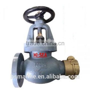
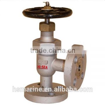
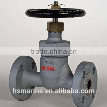
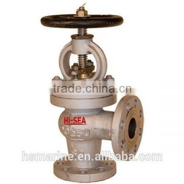
10.Drawing of Marine Cast Steel Flange Stop Check valve
Drawing of type A/AS:

Drawing of type B/BS:
11. Certificate available:
Contact Supplier

You May Like
New Products

Popular Searches
Recommended Products
Find Similar Products By Category
 Facebook
 X
X
 Pinterest
 Linkedln