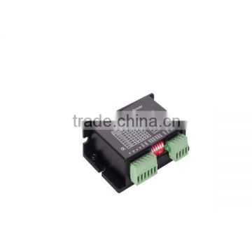
high speed ,2-phase Hybrid stepper motor driver,stepping motor driver for speedometer
USD $90 - $120 /Set
Min.Order:1 Set
Quick Details View All >
Changzhou Dewo International Trade Co., Ltd.
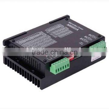
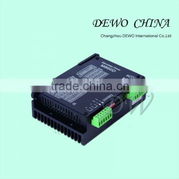
high speed .high power micro stepper driver M660A , ministepping driver
MA860H 2.6-7.2A AC Stepper Motor Driver For Nema23/34/42 AC18-80V DC24-110V DM860A

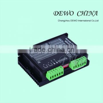
High torque,2-phase Hybrid stepper motor driver,12v linear actuator
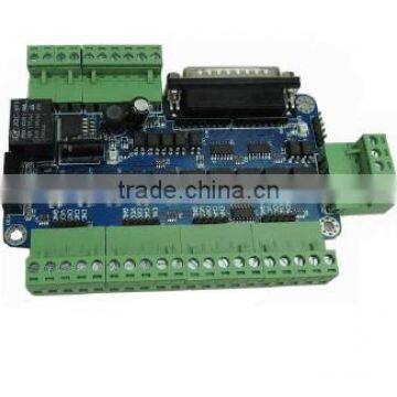
closed loop step motor driver DM556D with high performance,cnc machine parts driver

closed loop stepper motor driver using new 32-bit DSP ,high torque electric stepping motor driver
Product Details
Driver functions descriptions
Driver function | Operating instructions |
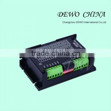
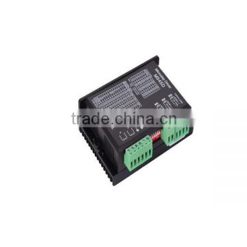
Output current setting | Users can set the driver output current by SW8-SW10 three switches. The setting of the specific output current, please refer to the instructions of the driver panel figure. |
Microstep setting | Users can set the driver Microstep by the SW1-SW5 five switches. The setting of the specific Microstep subdivision, please refer to the instructions of the driver panel figure. |
Single/double Pulse setting | SW7 sets pulse mode, setting “on” as double pulse mode, setting “off” as pulse + direction mode. |
Self-test setting | When SW1-SW5 five switches are all on “off”, the driver will test the motor normal or not according to the inner 1KHZ pulse. |
Automatic half current function | Users can set the driver half flow function by SW6. "OFF" indicates the quiescent current is set to half of the dynamic current, that is to say, 0.5 seconds after the cessation of the pulse, current reduce to about half automatically. "ON" indicates the quiescent current and the dynamic current are the same. User can set SW6 to "OFF", in order to reduce motor and driver heating and improve reliability. |
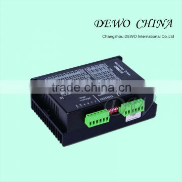
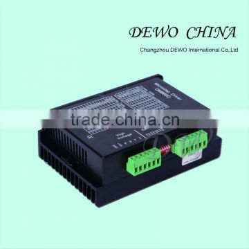
Signal interfaces | PUL+ and PUL- are the positive and negative side of control pulse signal; DIR+ and DIR- are the positive and negative side of direction signal; ENA+ and ENA- are the positive and negative side of enable signal. |
Motor interfaces | A+ and A- are connected to a phase winding of motor; B+ and B- are connected to another phase winding of motor. If you need to backward, one of the phase windings can be reversed. |
Power interfaces | It uses AC power supply. Recommended operating voltage is 110VAC-220VAC, and power consumption should be greater than 500W. |
Indicator lights | There are two indicator lights. Power indicator is green. When the driver power on, the green light will always be lit. Fault indicator is red, when there is over-voltage or over-current fault, the red light will always be lit; after the driver fault is cleared, if re-power the red light will be off. |
Installation instructions | Driver dimensions:198×130×76mm, please refer to dimensions diagram. Please leave 10CM space for heat dissipation. During installation, it should be close to the metal cabinet for heat dissipation. |
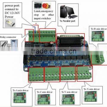
Control signal and external interface:
Signal amplitudes | External current limiting resistor R |
5V | Without R |
12V | 680Ω |
24V | 1.8KΩ |
Outline and installation size (unit:mm)

Signal interface details:
The internal interface circuits of the driver are isolated by the opt coupler signals, R in the figure is an external current limiting resistor. The connection is differential. And it has a good anti-jamming performance.
Contact Supplier

You May Like
New Products

Popular Searches
Recommended Products
Find Similar Products By Category

 Facebook
 X
X
 Pinterest
 Linkedln